Knowledge - Basic Cleanroom Layouts
You get asked to sketch or draw an example cleanroom layout in the viva.
This example is not comprehensive or exhaustive, or even that elegant. The goal is to give you something that can be:
Sketched quickly
Adapted to specific requests (see below)
Talked to at length if required
A systematic approach to cleanroom design
This is a framework to let you put something on paper that you can then flesh out in detail, a framework concept that lets you demonstrate knowledge. If you need to learn more a look at Annex 1 will only illustrate basic requirements you need to meet but the ISPE has a much more comprehensive (but paywalled) guide here: Baseline Guide Volume 3: Sterile Product Manufacturing Facilities (Third Edition) page 113 (ispe.org). Your engineering department may have a copy.
The WHO also has good guides for non sterile cleanrooms who-good-manufacturing-practices-for-heating-ventilation-and-air-conditioning-systems-for-non-sterile-pharmaceutical-products-(part-2)-interpretation-of-guidelines.pdf. Happy reading!
Basic building block
The first stage is defining how a lower grade (Grade D) cleanroom would be accessed from a non classified area. A Grade D environment is generally a support area, depending on how your cleanroom is designed. This is the least clean area of the GMP requirements for sterile products. Here is a list of tasks that are typically performed in a Grade D cleanroom:
Cleaning of equipment
Handling of components, equipment, and accessories after washing (Storage too)
Assembly of cleaned components, equipment, and accessories before sterilization
At its core its a room. So we draw a box. The room has three supporting boxes bolted onto the end. One to move materials in, one to move materials out, and one for people transfer. Doors for each box to box connection. MAL = Materials Airlock, PAL = Personnel Airlock.

It is possible for older cleanrooms to have a single MAL but that requires procedural separation of incoming and outgoing material and would not be considered acceptable if designing a cleanroom for sterile applications today. It is also possible (particularly in smaller cleanrooms for things like cell culture) that a MAL may be a small hatch system built into a wall with the incoming transfer sitting above the outgoing hatch. But you try drawing that simply in 2D.
This simple layout lets you talk to several other concepts that can be simply added as per below. I have added
Arrows to indicate personnel and material flows.
Pressure differentials relative to the controlled unclassified area “outside” the cleanroom
In general you want a differential that is a minimum of 10pa between grades, running at a 15pa setpoint gives some cushion when doors are opened etc
Hatches between grades are at a intermediate pressure differential - something recommended by the ISPE - which lets you have a constant cascade of air pressure to keep airborne dust moving from one zone to another.

In general this will not be sufficient for most questions. You will want to build up to a grade C cleanroom at minimum.
At this point the pattern is just repeated to the left of the existing diagram as below. The Grade D room becomes a support corridor. An extra set of MALs and PAL are added.

This has a lot more general utility as a cleanroom. A Grade C cleanroom can be used for performing lower risk steps of sterile product manufacturing. Here is a list of tasks that are typically performed in a Grade C cleanroom:
The filling of products for terminal sterilization (Min Grade C required for human products, Grade D may be acceptable for veterinary products).
Products with risks of microbial contamination should be prepared in a Grade C area.
Preparation of solutions to be sterile filtered, including weighing and dispensing of powders into liquids.
There is also the opportunity to cover the required procedural controls that will be required to move people and materials to a from the Grade C area - namely a heightened level of personnel gowning and additional cleaning of material surfaces and/or removal of outer packaging as required.
Finally it is possible to repeat the process yet again and add another box on the end and more airlocks. That lets us include a Grade B room in the same drawing.
The Grade B cleanroom environment of your GMP facility is used for aseptic preparation and filling. Strictly speaking it is the necessary supporting environment for Grade A enclosures or filling lines where sterile product or product contact parts may be exposed to air. The Grade B room will be used to transport (while protected from the surrounding environment) equipment, components, and ancillary items for introduction into the Grade A zone.
Grade B areas are supplied with HEPA filtered air that is typically the same quality (at the filter face) as that used in a Grade A area but the overall air quality will be lower due to the number of air exchanges per hour in the space, the turbulent nature of airflow and the presence of more contamination sources - primarily people.
As with each of the preceding stages we have unidirectional flow paths for materials in and out - which minimised cross contamination risks, but the personnel airlock is slightly more complex as it is recommended to provide unidirectional personnel flow. you also need to account for operatives that may need to temporarily leave the Grade B to change gloves as required.
I have snuck in an extra box - to symbolise an autoclave - which may be used to sterilise material coming into the area - or to terminally sterilise material coming out.

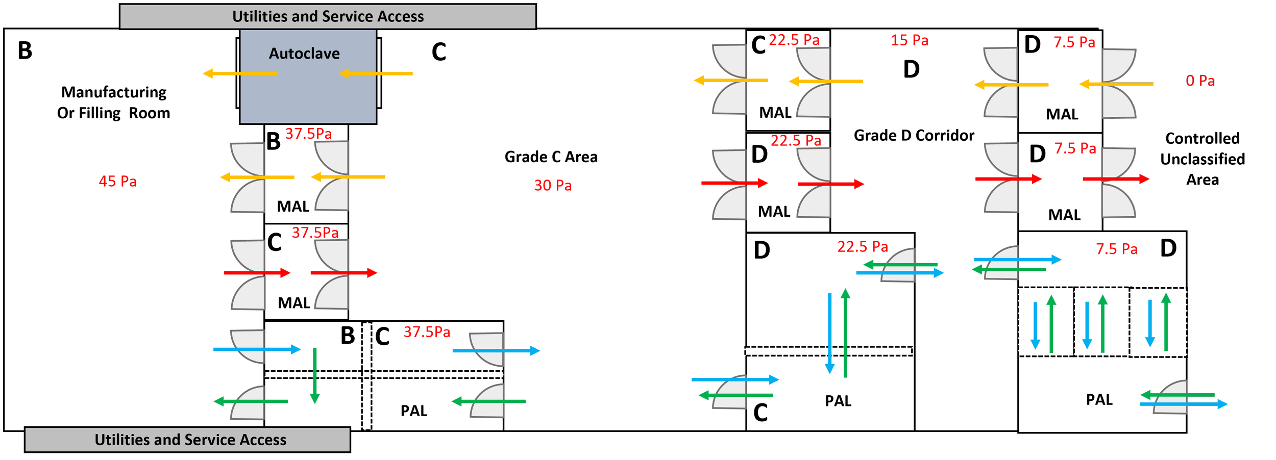
Finally in the image above I have added in some additional detail. Namely:
A linear design lets you add viewing areas which encourages good cleanroom behaviours and lets you record aseptic process simulations without additional equipment or personnel in the cleanroom
Placing key equipment near the walls lets services be accessible for routine maintenance without requiring cleanroom access. Again, this limits activity in the cleanroom to essential maintenance only.
Adapt as you go.
The general layout is not perfect - in practice you may want a separate, more direct change route for your Grade B personnel, but once you have it down you can adapt as you go. A further example below.

In the incarnation above I have added in some functional detail. Namely:
The single grade C change could support multiple rooms of activity - the manufacturing room is at a slightly higher pressure relative to the corridor to help manage airborne contamination
The washroom is at a lower pressure to the corridor. This is a justifiable practise to limit the egress of bioburden from this area into the general workspace. Again, in an ideal scenario you may use a dedicated change area.
Ultimately no design you can draw in ten minutes will be perfect or elegant but i think the approach outlined above is a approach easily retained and talked to.
If you want to have a play
The power point file i’ve used for the simple graphics is attached here.
Disclaimer
This document is not a legal document not should it be interpreted in any fashion as a guide. This is a set of notes compiled as part of a personal training program. It is not complete or authoritative. I hope it gives you some value.
This is a personal effort and is not affiliated with my current role or employer.
This work is licensed under a Creative Commons Attribution-NonCommercial-ShareAlike 4.0 International License. If you use it to train someone else, fantastic, but give the QP Notebook a plug. Thanks